


|
Power Source with Battery Back-up |

|
Got a Question or Comment? Ask Here!! Just CLICK the Wizard |
The plans provided here are for the 12 Volt DC Power Source used on the equipment racks at my house. This device provides 12 Volts DC for both operating the systems and keeping a back-up battery charged for cases when power may be disrupted.
|
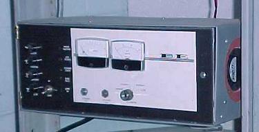
The Power Source is shown on the right as it is mounted in the rack. If you use the schematic to construct one of your own you may wish to modify the physical layout to suit your needs.
The battery is not shown in the photograph. It is located below the supply in the rack. A terminal strip on the rear of the power source provides connections to the battery and the loads. |
|
The case is hinged on the left and opens to allow access to the internal components. All controls, fuses, and indicators are mounted on the door.
A schematic of the power source is provided below. You can save it and refer to it as the operation is described here.
There are two primary circuits associated with this power supply. The first is the source itself. 18 Volts DC is supplied by the rectifier. This is passed through a shunt resistor which develops a voltage proportional to the current through it. Q2, in conjunction with the setting of the current limit control will turn on if the voltage exceeds the reference. This will occur if the current demand is greater than that set by the control.
Should that condition occur, Q2 will pull the voltage reference to the pass transistors low, which will reduce the voltage supplied from the source. This in turn will limit the available current from the unit. Current limiting is achieved in this manner.
Voltage regulation is accomplished by Q3, which establishes a fixed reference voltage. The voltage control uses this reference to set a fixed voltage on the base of Q4. This establishes a reference to the pass transistors which is independent of the load. The reference is only lowered in event the current limit is exceeded.
A steady DC output is supplied to the battery through F2 / F1. An ammeter will show the charge current at all times. It does not reflect the actual load however since at times the load may be supplied by the battery depending on demand and supply conditions.
An alarm and sense circuit is also provided. This will monitor the status and provide several functions. First, in event of line failure, it will switch on an auxiliary lighting output which can be used to supply emergency lighting. This output is only active during power loss conditions.
It will also detect a low battery voltage . A relay and indicator will activate under those conditions. The reference point can be adjusted using the control.
The system is designed to use a standard lead acid battery or gel cell. The amp-hour rating is not critical; However larger batteries will require additional time to reach full charge. The advantage of larger batteries is extended operation in event of power failure. The power source is rated at up to 10 amps at 12 volts DC Output. Loads rated near this will also require longer time to recharge the batteries after a power outage since the output is divided between the battery charging and supplying the load.