
Controls |

|
COMMENT??? Got A Question??? A Click on the Wizard opens Technical questions are welcome |
This page provides a basic block diagram and explanation of the control system used to operate the Active Solar Heat System. It is helpful in understanding how the various components are interconnected to form a functioning system. The system is broken down into 3 major components with description of each to follow. The drawing below is used as a reference in the text.
FURNACE BLOCK - The furnace block is responsible for heating the house. It works in conjunction with the solar storage to provide this heat. The temperature in the storage unit is checked by the Digital Controller. A determination is made as to how much, if any, supplemental electric heat is required to obtain a furnace plenum temperature of at least 100 degrees F. The required number of electric heating elements are then energized. The Digital Controller provides the sequencing of the electric elements necessary to prevent line surges on start-up.
There are two heating rates available from the furnace. These are determined by the difference between the room temperature and the set temperature of the thermostat. If the thermostat setting is increased, the system will adjust itself and attempt to reach the new set temperature in 20 minutes. This time frame is provided to allow the system to gradually increase temperature in order to prevent a high electric demand. A high demand would cause the system to draw more on electric heat as opposed to solar heat from storage. This is because as a rule stored solar heat is not as hot as that available from up to 20 Kw of electric heat. It is the responsibility of the Digital Control Unit to perform the calculations needed to obtain the optimum source for the heat to raise the room temperature. The current room temperature; the outside temperature; storage and collector temperature; and the new desired temperature are all taken into account. The system will at all times attempt to obtain as much heat as possible from the solar collectors or storage and only supplement with electric to extent needed to maintain the set temperature. While we are discussing priorities for heat sources, it should be pointed out that if the fireplace is in use, its priority will be greater than the solar sources. This is done to allow the system to utilize that source whenever it is available. The fireplace has the capacity to heat the entire house, however in keeping with the "passive occupants" concept of the house, I just don't use it that often. The Digital Controller software therefore has the capability to use the heat when it is available, but it is not considered a primary heat source.
An additional function of the furnace block is to provide for air conditioning. This is a conventional central unit and utilizes the furnace blower and compressor just as any commercially available unit. It consists of an evaporator coil located in the furnace plenum, and an external condenser coil and compressor located outside.
SOLAR RECOVERY BLOCK - (Storage unit and Collectors) The Storage unit consists of a large thermal mass located in the basement of the house. It is made up of over 3000 sealed glass jars filled with water. The air from the collectors is circulated around these jars and the heat is transferred into the water. The controller operates the air handler which is responsible for directing the furnace return air either through the storage unit, or bypassing it if no solar heat is available or the system is in the air conditioning mode. There is also a motorized damper located in the storage unit to close the supply and return trunks to the collectors. This is done to prevent heat loss when the collectors are not receiving solar energy. The Digital Control Unit determines its status, open or closed, based on collector temperature versus storage temperature.
Air flow through the collectors is dependant on the temperature of the collectors as compared to the storage temperature. The Digital Controller will take both of these, perform a calculation, and establish the blower speed which provides for optimum heat retrieval. When no heat is needed, as in summer, provisions are made to dump the excess to prevent overheating the collectors. The controller will open the Heat Dump and run the collector blower any time the collector temperature exceeds 135 degrees F.
FIREPLACE BLOCK - The Digital Controller is used in the operation of the fireplace in order to allow both the main heat system and fireplace to be integrated into a single operating system. This function can be realized since the controller software is common to both. The Digital Controller measures the fireplace plenum temperature, and, when a fire is present, will open the outside air damper to provide combustion air to the fire. As the temperature in the plenum continues to increase, the controller will set the fireplace blower speed accordingly.
In summary, it is the responsibility of the Digital Control Unit to operate the system using a dedicated program. This report does not include a definitive description of the program, since changes are made from time to time as I experiment with different system parameters. The outline included here is representative of the typical operation of the system.
DIGITAL CONTROLLER - The Digital Controller itself is comprised of two parts. The main processor is located on an equipment rack where it is powered by a 12 Volt UPS Unit. This allows for its uninterrupted operation in event of power failure. By doing this, program data is preserved even though the heating system itself may not be operating. The controller utilizes an 8085 microprocessor, 8K of RAM, and 16K of ROM. (The operating program is located in the ROM Chips.) The system also provides for up to 16 separate 8-Bit Input and Output ports. These are fully decoded so it is not necessary to provide any additional logic functions at any peripheral device. Besides the digital I-O ports, there are 8 available analog inputs. They are used for resistive temperature sensors. An 8-channel analog to digital converter card performs the conversion of this data so the system can utilize it. A real time clock is incorporated into the controller as well.
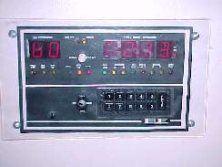
The wall thermostat is the status monitor of the system. Here various indicators show the current mode of operation the various major components in the system. Temperatures of the sensors throughout the system may be displayed. In addition, the internal clock makes it possible to program automatic temperature setting changes throughout the day allowing for complete automatic operation. Finally, the daily high and low temperature, as well as its time of occurrence, is recorded and may be recalled later.
Alarms are also reported here. In event one of the systems experiences difficulty a numeric code is displayed along with an audible alarm. Depending on the nature of the alarm some corrective measures may be initiated from this panel.