
Solar Heat Destination |

|
COMMENT??? Got A Question??? A Click on the Wizard opens Technical questions are welcome |
Welcome! This is the Main Solar Topics Page. The Buttons on the left provide a direct link to each of the primary sub-systems used in the Solar Heat system. If you would like to take a "Tour" of the entire system, simply click the "NEXT PAGE" Button at the bottom of each page. The Tour begins HERE with the Summary Report and Overview of the system.
The Sub Sytems are:
- Collectors - Heat recovery system and its operation
- Storage - System which saves excess heat for use at a later time
- Aux Heat - Supplemental electric furnace and woodburning fireplace
- Controls - The computer system which coordinates operation of all systems
- Water Heater - The Solar domestic water heater system
- More Information - Frequently Asked Questions and how you can order more in-depth information regarding what you have seen here.
And for the younger viewer, there is a special series of pages just for you. The Wizard explains the basics of Solar Heating, then gives you the opportunity to test your knowledge. A Click on the button will summon the Wizard. Go ahead, he's not doing anything anyway!!!
Enjoy you visit to this Destination!
System Overview
- Goals and Conclusions
Most articles dealing with topics of this nature provide "how to"
instructions, give details on a "just completed" project, or
maybe the latest technological innovations. What is not usually found
is a critical look at a system which has been in operation for a
number of years and an evaluation of how it has performed. Did it meet its original goals? Has it been cost-effective? Any unforeseen
problems encountered? Is it still viable today? This page will attempt to answer some of these questions and maybe pose some new ones.
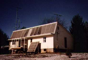
Photo of the back of the Solar House. The collector array
for space heating is located on the roof. The smaller unit
on the ground is for the solar water heater.
Background and Design Criteria
Before we can determine whether the system has performed as expected, we need to look back at conditions in the mid 1970s when the system was conceived. Oil shortages had drastically increased the price of fossil fuels. Electric rates were increasing rapidly. Inflation was in the double digits and was expected to continue this way for some time. Society had also begun to recognize environmental concerns. Commercially available active solar heat systems could cost as much as 20 - 30 thousand dollars installed. Passive systems could be done somewhat less, but they required continued interaction by the user for optimum performance.
Needing a house and with these factors in mind, I designed one specifically for solar heating. (fig 1) Next, I went to work on the design of a low cost solar heating system which could be home built. In order to keep cost at a minimum, I chose a slightly less efficient single glazed forced air collector array. The lower efficiency was offset by an increase in the surface area of the collectors. A reflective surface below the collectors also increased their heat gathering abilities.
A second requirement was minimal user intervention which is why the active system was chosen. I did not want to be involved with operating the system once the temperature requirements were set. I like the idea of programmed temperature and time settings. Just let the system take care of itself. Because of my background in electronics, I was able to design and build a microprocessor based special application controller to do this at minimal cost.
Finally, at the time the house was built, the Alternate Energy Tax Credit was in effect. This helped to offset some of the initial costs involved in setting up the system.
figure 2
Heat is circulated to the house by the furnace blower. This heat may be either taken from storage or provided by the back up electric furnace. The air handler sets the return air path based on heat availability. Air returns directly to the furnace if no solar heat is available or through the storage unit when solar heat is present. A more complete description is provided in the Tour of the System.
Now that you are somewhat familiar with the system and what it was designed to do, the question is,"How has it done?" The answer to this is it has met its goal of providing 50 percent of the heat needed to heat the house, but...
Initially payback was estimated to be 5 - 6 years. However due to the fact that energy costs stabilized in the 1980s, this payback did not occur until the tenth year. Had costs continued to spiral as they did in the late 1970s, the 5 year estimate would have been on target. From an environmental point of view the system did succeed in cutting the use of non-renewable energy for heating in half.
The FRP (fiberglass reinforced plastic) panels used as glazing have a life expectancy of 15 - 20 years. They are now reaching this point and will soon need replaced. As they age, they become slightly less efficient at allowing sunlight to enter. Current estimate is a loss of about 10 percent. The current cost to replace them is about 700 dollars. This would be recovered in about 3 years at today's energy costs.
Since 1980, one panel has experienced damage. It was partially torn loose due to high winds in 1984. Repairs were made and no other modifications deemed necessary. Similar winds have not caused any damage since.
A modification was required to the storage assembly. The original design used a rock pile for thermal mass. This was found to have a problem with mildew when the storage was not used during the summer. In 1982 the rock was replaced with approximately 3000 water filled and sealed glass jars. (These were obtained at minimal cost - they were re-cycled!) The mildew problem was eliminated.
Regarding maintenance costs, after over 15 years of operation there have been no major expenses encountered. The glazing replacement is the first major expense to be considered, however this was anticipated back when the system was initially installed.
Finally, regarding the Digital Controller some expenses have been encountered. However these were related to experimentation and upgrades related to research on the system. These would not be expected in a similar system installed strictly to provide heat. There have been two cases of electronics related failure since the current controller went on line in 1985. The first occurred in 1993 and was the result of a nearby lightning strike. A voltage regulator and output latch chip were replaced. The second failure occurred in 1997 when an EPROM failed. Repair costs in each case were under 20 dollars in parts.
First, while not a part of the Solar Space Heating System, the water heater collectors use the same type FRP panels for glazing. They too reached the end of their life expectancy. They have been replaced with double glazed tempered glass panels. (Since 1980, when I built the original collectors, I have found a source for these on the salvage market. I am using recycled patio glass door panels.) These were placed on the water heater collectors since they will benefit most from the increased operating temperatures expected. They also experienced more degradation than the space heating panels due to higher operating temperatures.
Another digital controller upgrade has eliminated the need for a separate controller for the solar water heater. The upgraded space heating controller now performs and monitors these functions as well as all space heating requirements. The upgrade consisted mainly of programming changes with minor hardware modifications.
The glazing on the space heating collectors will be replaced. Whether glass panels on FRP panels are used depends on results of tests done with the upgraded solar water heater collectors. The double glazed tempered glass panels are the preferred replacement as of now since they are more efficient and, in my case using salvaged panels, actually cheaper than FRP panels.