
Water Heater |

|
COMMENT??? Got A Question??? A Click on the Wizard opens Technical questions are welcome |
This page covers the updated Solar Water Heater system. It includes documentation of the revisions placed in service in the summer of 1998.
SOLAR WATER HEATER - The Solar Water Heater is a liquid transfer preheater used in conjunction with an electric water tank to provide domestic hot water to my residence. The system supplies water at a temperature of greater than 145 degrees F. The basic operation involves the use of a solar collector, heat exchanger, pumps, and a storage tank to preheat the cold water coming into the house prior to sending it to the electric water heater. In an ideal situation, the temperature of the water leaving the storage tank will exceed the thermostat setting of the electric tank. This results in the electric tank functioning only as additional storage capacity. In reality, these conditions occur at times, but some electric assist may also be provided. This serves to reduce electric consumption even though the solar may not be capable of supplying the entire hot water demands at all times.
COLLECTORS - The collectors are flatplate, liquid type consisting of 78 square feet of surface area. They are covered by double pane glass panels to minimize heat loss and increase the collector operating temperature. These are salvaged patio door panels which were removed due to minor fogging. The fogging is not a significant problem in this application and, since they were to be discarded by the glass companies anyway, could be obtained for the right price (free!).
|
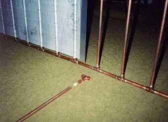
The absorber plates are
comprised of 3/8" copper tubing between an upper and a lower header pipe. Flow restrictors are placed in each tube to provide even distribution of fluid through all tubes. (Note the exploded view of a tube assembly in front of the panel in fig. 1.) Aluminum sheets, obtained from the local newspaper printer who used them in the printing process, are pressed around the copper |
|
|
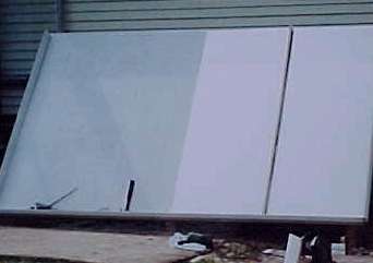
Figure 2 shows the basic collector box before the installation of the absorber plates. The insulation panel has been installed on the right side. |
|
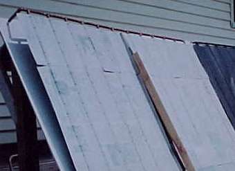
Shown here is a photo of the absorber plates as they are placed in the collector box. The one on the right has been painted, while the left side shows the aluminum sheets as they come from the newspaper printer. |
|
This configuration heats the glycol to as much as 155 degrees F., or about 20 - 25 degrees hotter than the earlier system which used a slightly larger collector but had only a single sheet of fiber glass reinforced plastic as a cover. The earlier system was replaced due to degradation of the FRP sheets from UV radiation. They did, however, meet their life expectancy of 15 years. Long term evaluation of the new collectors has begun, but the results are not yet available. There has been no sign of problems to date.
Inside the house, a heat exchanger transfers the heat from the glycol to the hot water system. The photo below shows how the heat exchanger is built. A half inch copper tube is placed inside a three quarter inch tube and reducing tees are placed at each end. The tees allow the two fluids to flow on each side of the half inch tube and the heat is conducted through the wall of the tube. Note the detail of the fittings on the left in the photo below.
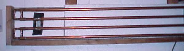
figure 4
A description of the entire system follows. Refer to the system diagram below to locate the major components as the description is given.
System Diagram
Pump P-1 circulates the glycol from the collector to the heat exchanger and back. An expansion tank is included in this loop to prevent pressure build up. The tank also includes a sight glass and filler in order to check and replace the glycol as needed. An air purge provision is made in the pipe near the top of the collector. This will remove any air which accumulates in the glycol side of the water heater. The heat exchanger transfers the heat from the glycol side to the water side. Pump P-2 circulates the water from the storage tank through the exchanger where it picks up the heat and back to the tank. A system drain is provided to allow the glycol to be easily replaced without the need to disconnect any pipes.
The control unit is a differential thermostat which compares storage tank temperature with the collector temperature. It uses the results of this comparison to determine the optimum pump speed; high, low, or off. The command to pump P-2 is delayed 10 seconds after pump P-1 to allow for the heat transfer lag through the heat exchanger. Provisions are also included to monitor the status of the electric tank. (on or off)
Currently, the Solar Water heater system operates completely independent of the space heat system discussed elsewhere. This system obtains 70 - 80 per cent of its output from its solar collectors. Since this system first went on-line in 1982, the solar storage tank has been replaced; a change was made from a 40 gallon to the 80 gallon tank, and the collectors have been upgraded in 1998. The collector upgrade was done, as stated earlier, due to degradation in the original FRP glazing and to increase the system performance.
Control of the Water Heater is accomplished by the same system which operates the primary heating system. The water heater status is displayed on the thermostat / display panel. This integrated control has simplified operation of both systems by eliminating the need for a second solar control unit.
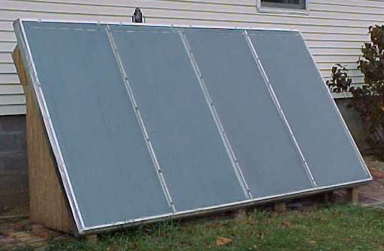
The completed Solar Water
Heater collector unit